The Kelvin Bridge is a variation of the Wheatstone bridge which enables low resistances to be measured. The measurement range would typically be 1mΩ to 1kΩ with the smallest resolution of 1µΩ.
The limitations of the Kelvin bridge are:-
- requires manual balancing
- sensitive null detector or galvanometer is required to detect balance condition
- measurement current needs to be reasonably high to achieve sufficient sensitivity
The Kelvin Double Bridge has generally been replaced by digital ohmmeters.
DMM - Two-wire Connection
A simple digital multimeter can be used for higher values of resistance. They employ the 2 wire method of measurement and are only suitable for measuring values above 100Ω and where high accuracy is not required.
When measuring the resistance of a component (Rx) a test current is forced through the component and the test meter measures the voltage at its terminals. The meter then calculates and displays the resulting resistance and is known as a twowire measurement. It should be noted that the meter measures the voltage at its terminals and not across the component. As a result of this, the voltage drop across the connection leads is also included in the resistance calculation. Good quality test leads will have a resistance of approximately 0.02Ω per meter. In addition to the resistance of the leads, the resistance of the lead connection will also be included in the measurement and this can be as high as or even higher in value than the leads themselves.
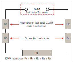
When measuring larger resistance values this additional lead resistance error can be ignored, but as you can see from the chart below, the error becomes significantly higher as the measured value decreases, and totally inappropriate below 10Ω.
TABLE 1
Examples of possible measurement errors

To measure true DC, resistance ohmmeters typically use 4 wire measurement. DC current is passed through the Rx and through the ohmmeter’s internal standard. The voltage across the Rx and the internal standard is then measured and the ratio of the two readings is used to calculate the resistance. With this method the current only needs to be steady for the few milliseconds required for the ohmmeter to make both readings, but it requires two measurement circuits. The voltage measured is very small and a µV measurement sensitivity is usually required.

Alternatively a constant current source is used to pass a current through the Rx. The volt drop across the Rx is then measured and the resistance calculated. This method requires only one measurement circuit but the current generator has to be stable under all measurement conditions.
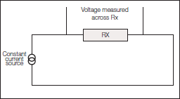
Four wire connection
The four wire (Kelvin) method of measurement is preferred for resistance values below 100Ω, and all Cropico milliohmmeters and microhmmeters use this method. These measurements are made using 4 separate wires. 2 wires carry the current, known as the source or current leads and pass current through the Rx. The other 2 wires known as the sense or potential leads, are used to sense the
voltage drop across Rx. Whilst some small current will flow in the sense leads, it is negligible and can be ignored. The volt drop across the ohmmeter’s sense terminals is therefore virtually the same as the volt drop across Rx. This method of measurement will produce accurate and consistent results when measuring resistances below 100Ω.

From a measurement point of view this is the best type of connection with 4 separate wires; 2 current (C and C1) and 2 potential (P and
P1). The current wires must always be placed outside the potential although the exact placement is not critical. The potential wires must be connected exactly at the points you want to measure between. The measured value will be between the potential points. Whilst this gives the best measurement results it is often not practical. We live in a non perfect world and sometimes small compromises have to be made, Cropico can offer a number of practical measurement solutions.
METHODS OF 4 TERMINAL CONNECTIONS
Kevlin Clips
Kelvin clips are similar to crocodile (Alligator) clips but with each jaw insulated from the other. The current lead is connected to one jaw and the potential lead to the other. Kelvin clips offer a very practical solution to making a four terminal connection to wires, busbars, plates etc.

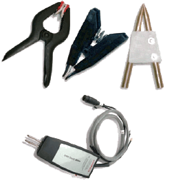
Duplex Handspikes
Handspikes offer another very practical connection solution particularly for sheet material, busbars and where access can be a problem. The handspike consists of two sprung spikes enclosed in a handle. One spike is the current connection and the other is the potential or sense connection.

Stacked Lead connection
Sometimes the only practical solution to making a connection to the Rx is to use stacking leads. The current lead is pushed into the back of the potential lead. This method will give small errors because the measurement point will be where the potential lead connects to the current lead. For measurement of awkward-to-reach samples, this can be the best compromise solution.

Cable clamps

When measuring cables during manufacture, and for quality control purposes, it is necessary to maintain consistent measuring conditions. The length of the cable sample is normally 1 metre and to ensure that accurate 1 metre lengths are measured, a cable clamp should be used. Cropico offer a variety of cable clamps which will accommodate most cable sizes. The cable to be measured is placed in the clamp and the ends of the cable are clamped in the current terminals. The potential connection points are normally in the form of knife edge contacts which are exactly 1 metre apart.

Jigs and fixtures
When measuring other components such as resistors, fuses, switch contacts, rivets etc. the importance of using a test jig to hold the component cannot be emphasised enough. This will ensure that the measurement conditions, i.e. position of measurement leads, are the same for each component which will result in consistent, reliable and meaningful measurements. Jigs often have to be specially designed to suit the application.
POSSIBLE MEASUREMENT ERRORS
There are several possible sources of measurement error associated with low resistance measurements. The most common ones are described below.
Dirty connections
As with all measurements, it is important to ensure that the device you are connecting is clean and free from oxides and dirt. High resistance connections will cause reading errors and may prevent measurements. It should also be noted that some coatings and oxides on materials are good insulators. Anodising has a very high resistance and is a classic example. Be sure to clean off the coating at the connection points. Cropico ohmmeters incorporate a lead error warning which will indicate if the connections are too high in resistance.
Resistance of leads too high
Whilst in theory the four terminal method of measurement is unaffected by lead length, care must be taken to ensure that the leads are not too high in resistance. The potential leads are not critical and can usually be up to 1kΩ without affecting the measurement accuracy, but the current leads are critical. If the current leads are too high in resistance then the voltage drop across them will result in insufficient voltage across the DUT (Device Under Test) to make a sensible reading. Cropico ohmmeters check this compliance voltage across the DUT and prevent a measurement from being made if it falls too low. A warning display is also provided; preventing the reading, ensuring that false measurements are not carried out. If you need to use long measuring leads, then increase the diameter of the cables to reduce their resistance.
Measurement Noise
As with any type of low voltage measurement, noise can be a problem. Noise is created within test leads when they are in the influence of a magnetic field which is changing or the leads are moving within that field. To minimise this effect, leads should be kept as short as is practical, kept still and ideally shielded. Cropico realises that there are many practical constraints on achieving this ideal, and have therefore designed the circuits within their ohmmeters to minimise and eliminate these effects.
Thermal emf
Thermal emf in the DUT is probably the biggest cause of errors in low resistance measurements. We must first understand what we mean by thermal emf, and how it is generated. Thermal emfs are small voltages which are generated when two dissimilar metals are joined together, forming what is known as a thermocouple junction. A thermocouple will generate an emf depending upon the materials used at the junction and the temperature difference between the hot and the reference, or cold, junction.


This thermocouple effect will introduce errors into the measurement if steps are not taken to compensate and eliminate these thermal emfs. Cropico microhmmeters and milliohmmeters eliminate this effect by offering an automatic average mode for the measurement, sometimes called the switched DC or average method. A measurement is made with the current flowing in the forward direction then a second measurement is made with the current in the reverse direction. The value displayed is the average of these two measurements. Any thermal emf in the measuring system will add to the first measurement and be subtracted from the second; the resulting average value displayed eliminates or cancels the thermal emf from the measurement. This method gives the best results for resistive loads but is not suitable for inductive samples such as motor or transformer windings. In these cases the ohmmeter is likely to switch current direction before the inductance is fully saturated and the correct measured value will not be achieved.
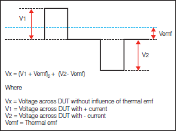
The second method sometimes employed is to connect the current terminals of the ohmmeter together, and with the potential leads connected to the DUT, measure any thermal emf that may be present. This measured value is then stored and deducted from the next measurement with current and potential leads connected to the DUT in the normal way. This is all done automatically when using Cropico Ohmmeters in the auto zero mode.
Thermal emfs can be relatively high (100mV) and it is therefore important to carefully select the materials used for making connections. Nickel plated brass, for example, can produce high emfs when forming junctions with copper. Crocodile clips are often made from nickel plated brass and can produce very high emfs when forming junctions with copper connecting wires.
Inappropriate connection to sample
When making four wire connections it is important to place each wire in the appropriate place. The current and potential leads should always be used in pairs and the current connection outside the potential as shown below.
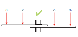
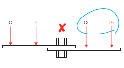
Measurement of joint resistance of 2 busbars
Wrong Test Current
Consideration should always be given to the effect the measurement current will have on the DUT. Devices with a small mass or constructed with materials that have a high temperature coefficient, such as thin strands of copper wire, will need to be measured with the minimum current available to avoid heating. In these cases a single pulse of current may be appropriate to cause the very minimum of heating. Should the DUT be subject to the influences of thermal emf then the switched current method described earlier is appropriate. The Cropico DO5000 series of ohmmeters have selectable currents from 10% to 100% in 1% steps, plus a single pulse mode and consequently may be configured to suit most applications.
Temperature influences
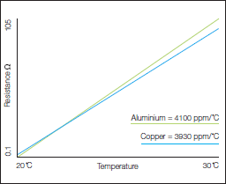
It is important to be aware that the resistance of most materials will be affected by their temperature. It may be necessary, depending upon the accuracy of measurement required, to control the environment in which the measurement is made, thus keeping the ambient temperature constant. This would be the case when measuring resistance reference standards which are measured in a controlled laboratory at either 20°C or 23°C. For measurements where controlling the ambient temperature is not possible, the ATC (automatic temperature compensation) facility can be used. A temperature probe, connected to the ohmmeter, senses the ambient temperature and the resistance reading is corrected to a reference temperature of 20°C. Two of the most common materials measured are copper and aluminium and their temperature coefficients are illustrated opposite.
The Temperature Coefficient of Copper (near room temperature) is +0.393 % per °C. This means if the temperature increases 1oC the resistance will increase 0.393%. Aluminium is +0.4100 % per °C.


Sign up to our Newsletter.
Stay up to date with the latest industry and product news, as well as our free educational content such as webinars and our expert guides.
Close